- 25 Jan 2025
- 9 Minutes to read
- Print
- DarkLight
Hardware Patch
- Updated on 25 Jan 2025
- 9 Minutes to read
- Print
- DarkLight
LED CTRL outputs either sACN or ArtNet and can therefore be used with any hardware controller that can receive ArtNet or sACN, but it works most seamlessly with our LED CTRL range of hardware devices. These devices provide a range of integrations that reduce double handling of patch/configuration info, providing faster configuration and less opportunity for errors in the configuration that take time to resolve.
For best integrations and hence easiest hardware configuration the MX96PRO/SX or PX24 devices are advised.
Network configuration
When the LED CTRL application starts up, it detects the presence of the LED CTRL license and the network settings of the machine's ethernet adapters. These network settings will determine what devices LED CTRL can detect, connect to and allow configuration of. Typically we recommend using a standard IP address for the LED CTRL master machine, and then a range of IP addresses in sequence for each hardware controller, such that the network addresses might be like:
LED CTRL Master: IP: 2.0.40.1 Subnet: 255.255.255.0
LED CTRL PX24 device: IP 2.0.40.2 Subnet: 255.255.255.0
LED CTRL MX96 device: IP2.0.40.3 Subnet: 255.255.255.0
Of course, your network topology might mean you need to conform to another range of IP addresses, but the devices will need to be configured such that they are accessible over the network.
Typically it's best to set your Master IP address to where it needs to be for your project, then configure the controllers to align to the master.
Setting your LED CTRL Master machine's network address
Depending on the platform you are using, the method for configuring network settings is a little different.
On a Mac: Open the System Settings app and select the Network option from the left hand pane:
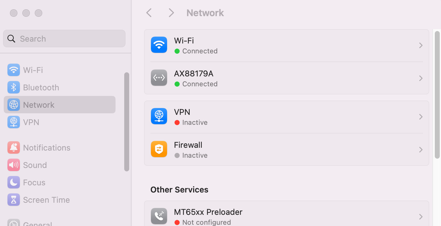
Select the connected network adapter (AZ88179A in the example above) to see the network settings:
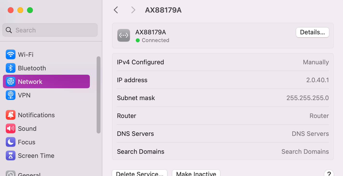
Select Details, followed by TCP/IP to alter and save as required:
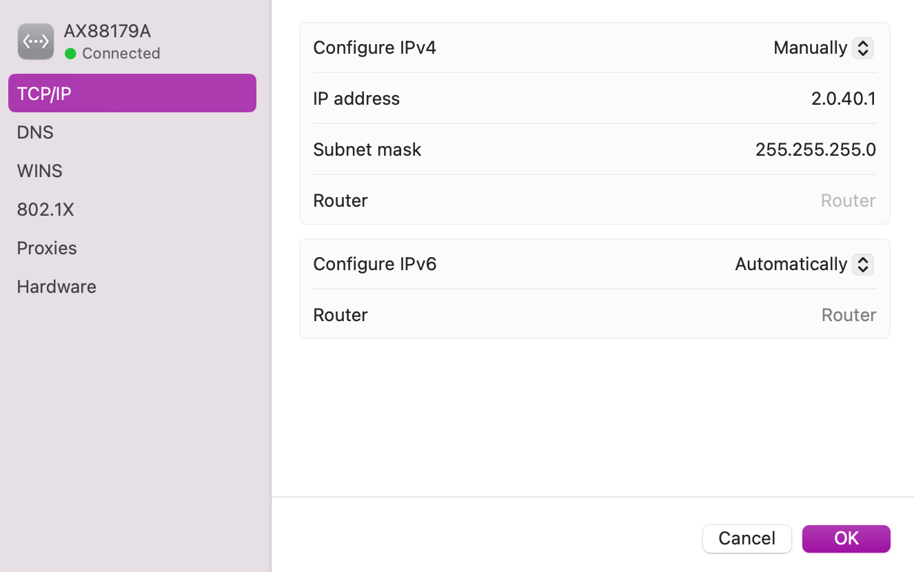
Starting LED CTRL and check Network Adapter detected
Having set the network correctly, and with the configured network port connected to your device, start (or restart) LED CTRL. LED CTRL detects available networks on startup, so the restart ensures that the new network settings are picked up.
Confirm the correct adapter is available open the Artnet Settings window using: File-> Settings ->ArtNet Settings...:
.png)
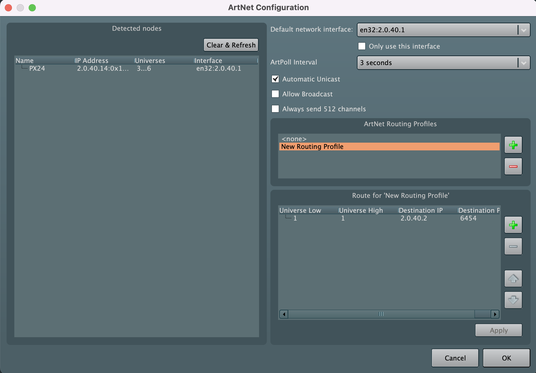
This opens the ArtNet Configuration window which shows the network adapters available, visible devices on the network and is where an ArtNet routing Profile is set (if not using LED CTRL MX/PX hardware).
At the top right of the ArtNet Configuration window, use the dropdown in the Default network interface to select the network adapter that you set up above (Note: on Linux devices you may need to restart the machine after changing the network adapter settings).
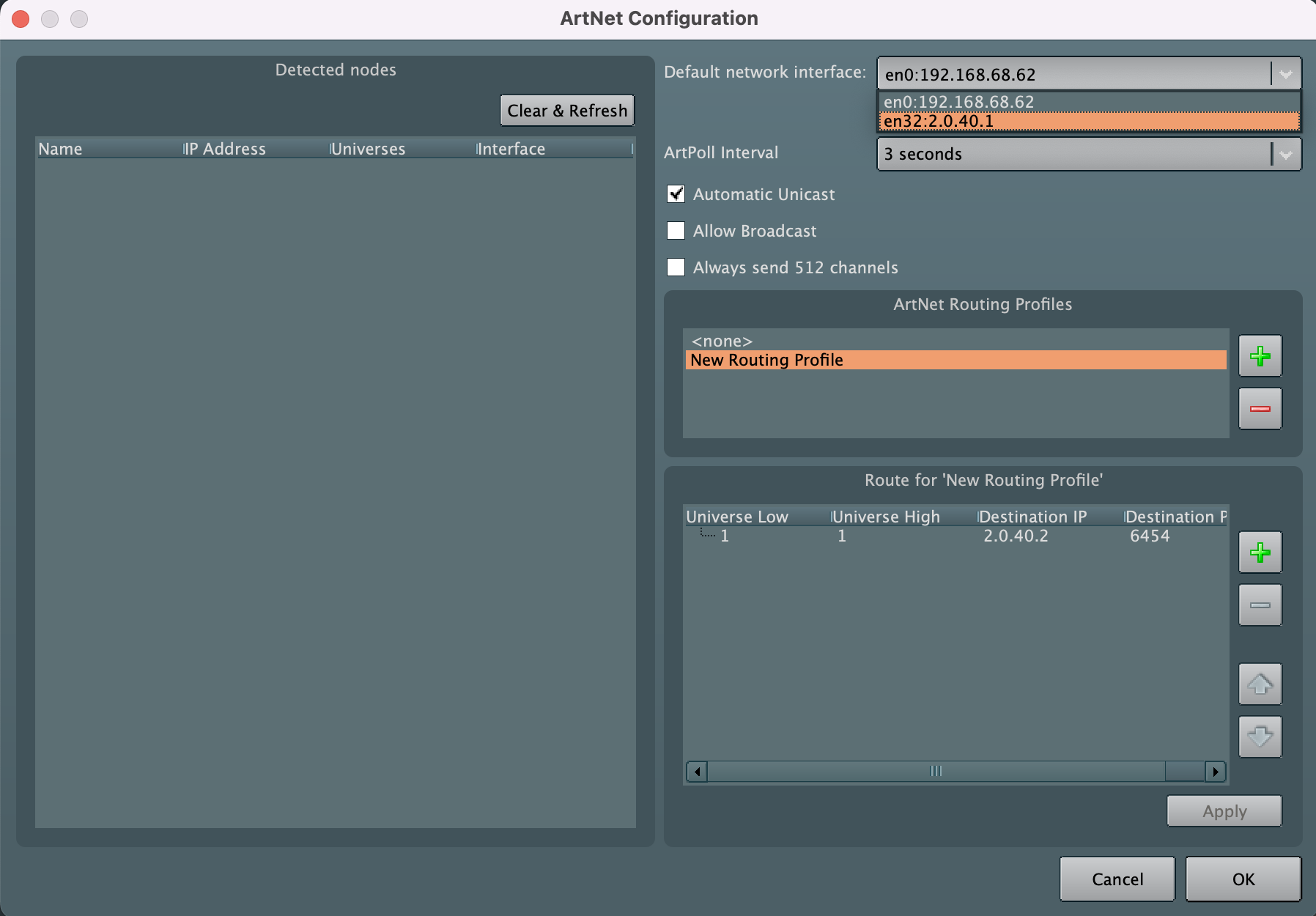
Once the correct network adapter has been selected, hit OK and save and restart your show to save this network adapter setting in the project file.
On restart, returning to the ArtNet configuration window will now show devices that are visible on the network in the left hand pane.
Enabling LED CTRL devices from within LED CTRL
LED CTRL PX/MX devices can be configured via their Web Management Interface as documented in the MX and PX quick start and configuration guides (available from ledctrl.sg/downloads/), however the easiest way to configure them in the majority of cases is via the Hardware Patch window.
Access the Hardware Patch window via the LEDs window Hardware button.

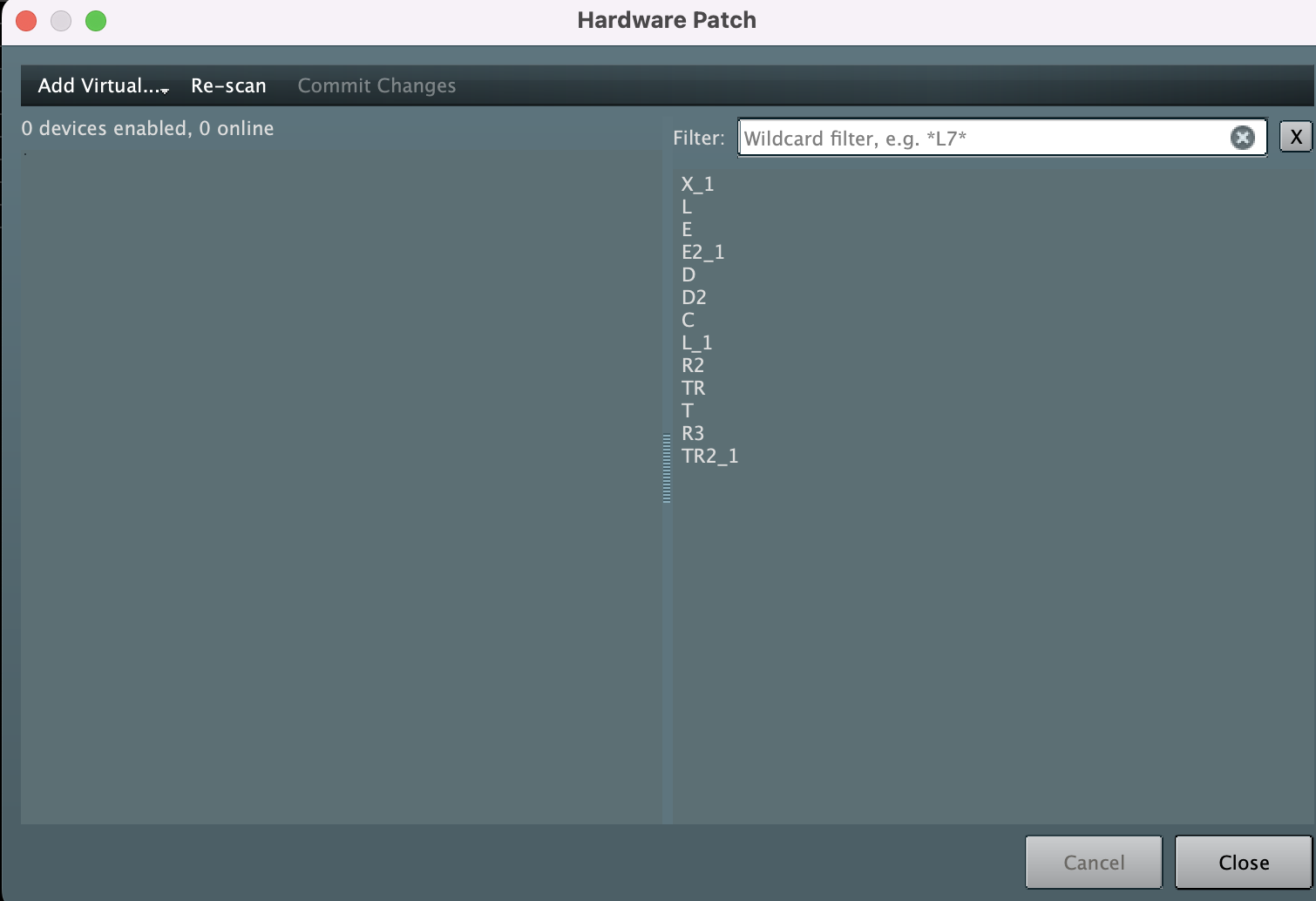
This will display the Hardware Patch dialog. From this dialog you can see which devices are connected and perform the bulk of configurations for MX96PRO and PX24 devices.
If there are no devices configured in the LED CTRL project file there will be no devices shown, as follows:
If devices are connected that are on a network that is not reachable by LED CTRL, the Change network parameters dialog will be shown (1 per device) to allow the device to be modified: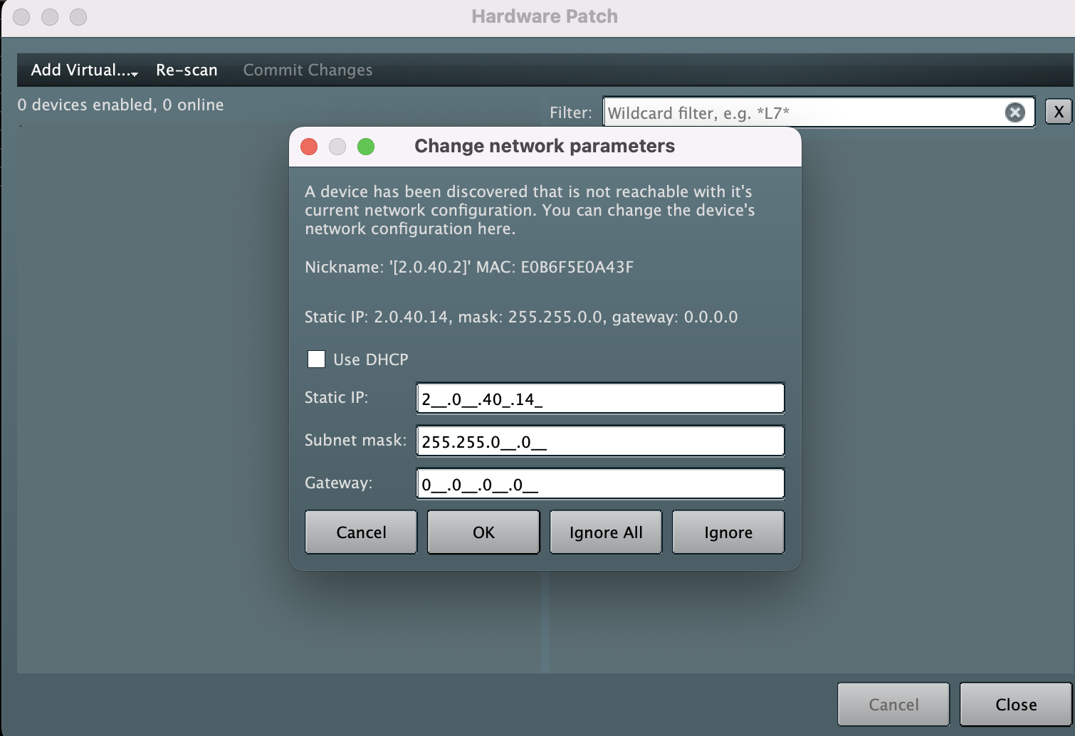
Note: Whilst DHCP can be used, we recommend using Static addresses for permanent installations, ensuring the network configuration is known and consistent to prevent hardware devices from disconnecting from LED CTRL and causing loss of control of fixtures. If using Static IP's be sure to deselect the Use DHCP tick box.
In the example above, the Subnet mask needs to be updated to match the computer settings of 255.255.255.0. 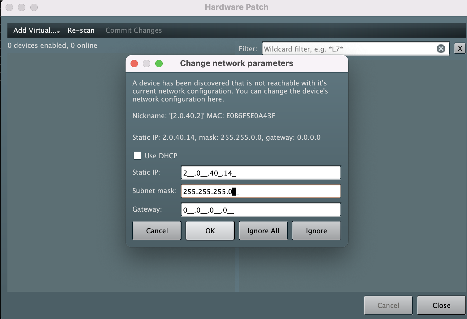
Once correct, select OK and the device will be shown on the Hardware Patch window left hand pane.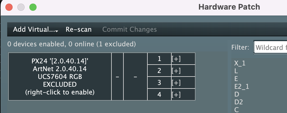
If expected devices are not detected initially, select Re-Scan to re-attempt to find them.
When devices are detected by a project for the first time, they will be shown as EXCLUDED from the configuration. Enable the device into the project file by Right Clicking on the device summary information, followed by Enable:
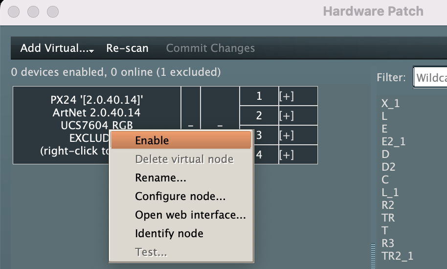
The Enable Node? dialog will be displayed where you can select how many universes should be assigned to this device. The defaults are PX=24, MX=96.
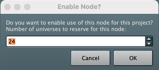
Select OK and the device will now be shown as Online. Now you can again Right Click the device summary information and select Configure node... to open the Hardware Configuration window: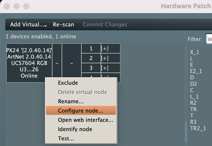
Hardware Configuration
The Hardware configuration window allows all the key settings of the PX/MX device to be set in LED CTRL and simultaneously be saved to the project file and the hardware device.
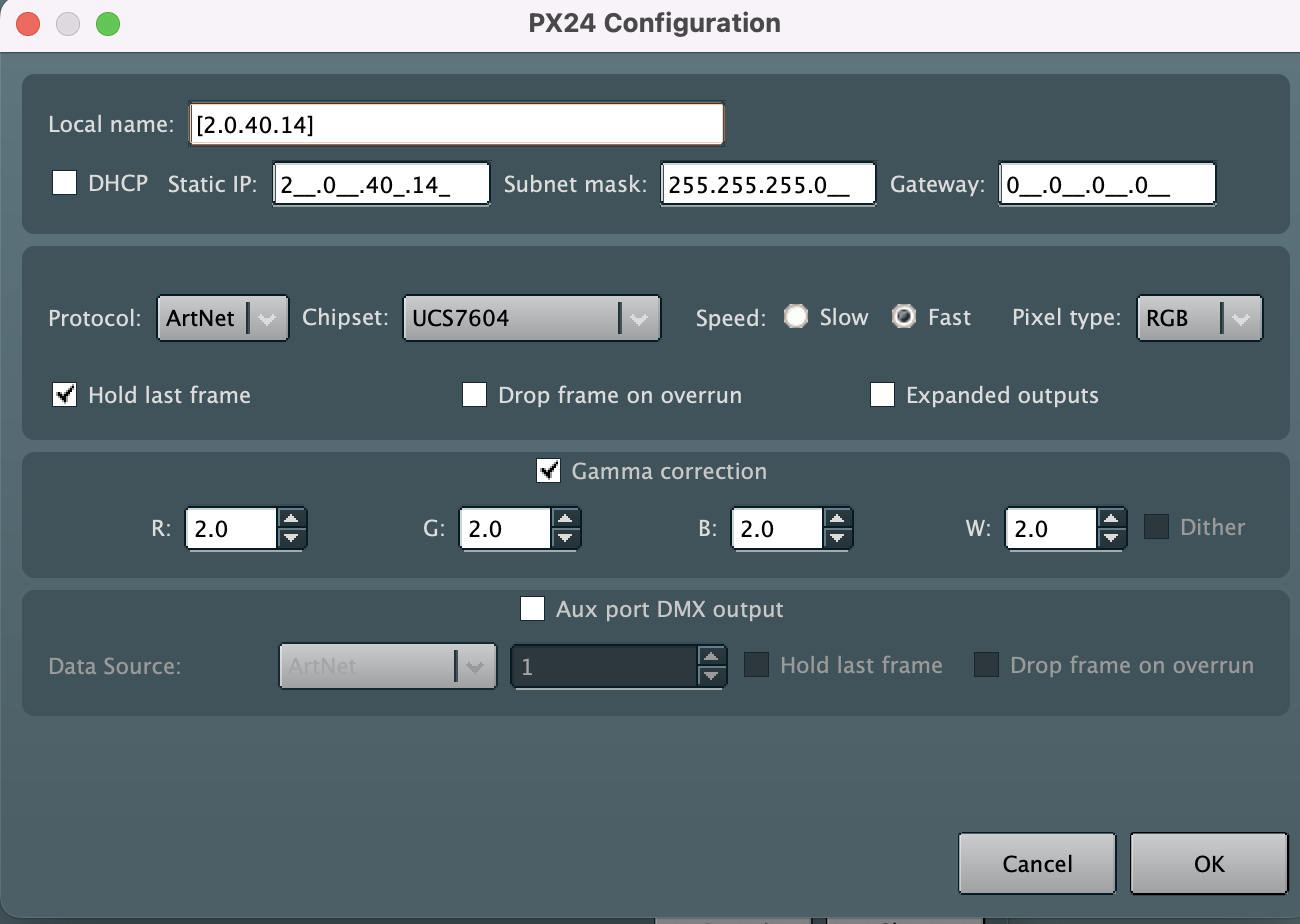
Make the changes to the device configuration to suit your project, the following settings are available:
- Local name: a user selectable name for the device.
- DHCP: Tick DHCP to allow a DHCP server (such as a router) to automatically assign IP address settings to the device (if the master computer is also using DHCP). If not ticked, the static IP address selected will be used.
- Static IP: Static IP is recommended. Complete the Static IP address, Subnet mask and Gateway. When allocating a static address, the IP address and the subnet mask both define the subnet that the device is operating on.
- Subnet: You need to ensure that other devices that need to communicate with this device are on the same subnet. Therefore, they should normally have the same subnet mask and a similar but unique IP address.
- Gateway: can be set to 0.0.0.0 if it is not required. If communication between the device and other VLANs or the Internet is required, the Gateway should be configured (and will typically be the IP address of the router)
- Protocol: Allows sACN or ArtNet to be used for communication to the device
- Chipset: Allows selection of the chipset for you fixtures. Note that all ports on a PX/MX device are configured to this chipset )not possible to configure per port)
- Speed: Allows selection of speed options when supported by the chipset (normally pixels wiht clock lines, or data only pixels that support multiple data transmission speeds. Faster clock speed can give a better refresh rate, but slower clock speeds can be beneficial for data integrity over long cable runs.
- Pixel Type: Allows selection of the colour type for the small number of chipsets that support both options.
- Hold Last frame: configures the device to hold the last received data frame on all pixel outputs if the input data is disconnected or lost. Disabling this behaviour will result in the device timing out and blanking all pixel outputs after a few seconds of not receiving any valid input data.
- Drop frame on overrun: In the event where an incoming frame on the pixel data source is received during a previous frame's processing/outputting time, "Drop Frame on Overrun" configures the device to drop the incoming frame. This can assist in maintaining synchronisation of outgoing frames to the pixels, by removing the need for the processor to catch up when it is overrun with frames. By enabling this option, the processor will instead drop these frames, which may lower the outgoing pixel frame rate. An example where this option may be beneficial is when a pixel grid exhibits 'tearing' - "Drop Frame on Overrun" can help reduce these effects, by attempting to maintain synchronisation. If disabled, the device will not drop a frame in the event of overrun data, unless two or more frames are received while still processing/outputting an old frame.
- Expanded Outputs: Pixel types that are data-only (no clock line) can allow use of expanded mode. This mode converts the unused clock line on each pixel output to instead function as a data output. This means that data-only pixels can be connected to either a data or a clock line, allowing more flexibility and the potential for higher refresh rates. The number of physical data outputs available is doubled, and the maximum number of pixels that can be connected to each output is halved. This means that the total number of pixels that the device can support remains the same, regardless of the status of expanded mode
- Gamma Correction: Gamma correction is the method used for correcting the output of the pixels so that they respond in a much more linear fashion when viewed by the human eye (the spectral response of the human eye is non-linear). This is particularly important when the pixels are being faded, and also provides more accurate and vivid colour representation. Pixels higher than 8-bit will turn on gamma correction by default, however this can be disabled if desired. Gamma Correction can also be enabled on 8-bit or lower pixels. Once enabled, the value of the gamma curve of each colour can be adjusted with the four R,G,B &W settings. Increasing these gamma values will increase the amount of correction applied to the output signal. Typically, a gamma corrected value of 2.0 is a good place to start
- Dithering: Pixels that have 8-bit colour resolution, with gamma correction applied, can benefit from the use of dithering. Dithering is a technique that creates additional “virtual” intensity levels. With dithering, a virtual midpoint between two intensity levels will be created by jumping back and forth between the two physical intensity levels very quickly. The rate at which this happens is faster than a human eye can detect, and so the resultant effect is an extra intensity level. Using dithering will generally allow the perceived resolution of gamma corrected 8- bit pixels to be higher, allowing for a smoother pixel system. For Dithering to function correctly, a high output frame rate is required. The feasibility and benefit of using the Dithering feature in your system will depend on many factors.
- Aux port DMX Output: LED CTRL allows the AUX port to be set to DMX Output (currently can't set to input from LED CTRL) with the configurations as selected.
Assigning Pixel Groups to Hardware
Once your device is enabled, you can add Pixelgroups that are not currently assigned, but dragging them from the right hand pane to the port you want them attached to on the left hand pane.
The Filter can be used to reduce the number of Pixelgroups shown.
Holding the CTRL key (Command on Mac) while selecting multiple Pixel groups in the right hand pane, will add the pixelgroups in the order they were selected.
Once added to a port, the Pixel groups are shown in the order in which they are daisy chained:
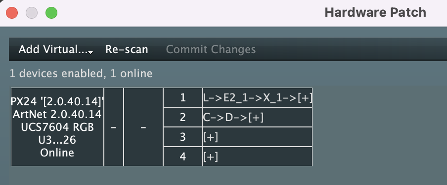
Changing Pixel Group assignment to Hardware
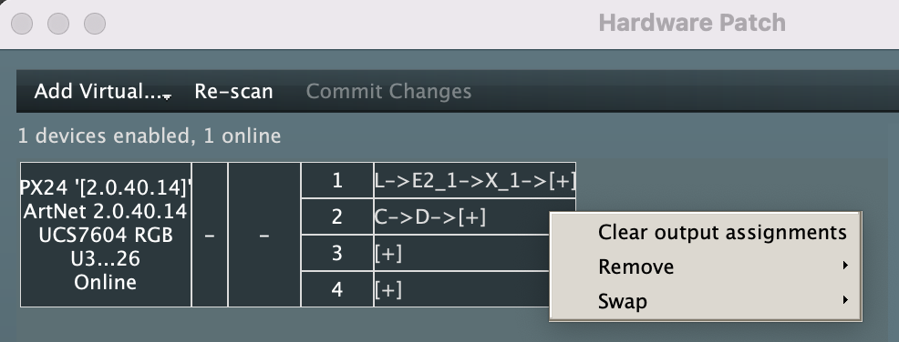
- Clear Output assignments: removes all pixelgroups from the selected port
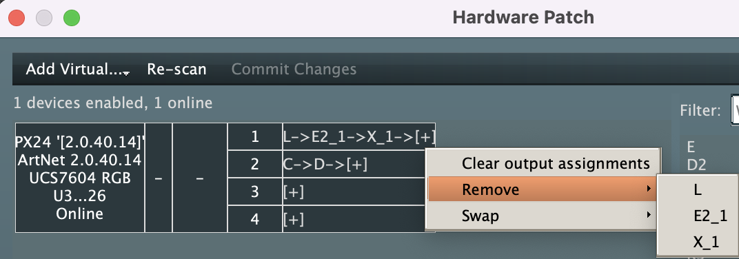
- Remove: Allows you to remove a specific Pixel group from a list. this is very useful when you have many fixtures making up the diasy chain and need to amend the order etc.
- Swap: Lets you move all Pixelgroups from one output to another - very useful when the ports have been physically plugged in differently to the way the job was planned.


